
Building a High Voltage Plasma Generator
The core concept is pretty straightforward: take a flyback transformer, which comes straight out of an old CRT television, and drive it with a ZVS (Zero Voltage Switching) driver board to produce extremely high voltages (~20,000 V). At that kind of voltage, air itself breaks down and becomes conductive, forming a glowing plasma arc between electrodes.
We couldn’t measure the voltage directly since no standard multimeter handles anywhere near that range, as most max out at 750V AC. Instead, we estimated it by measuring the arc length. Air breaks down at roughly 1,000 volts per millimeter under standard conditions, so a 20mm arc gives you a rough estimate of around 20,000 volts. That’s not exact, as humidity, electrode geometry, and air pressure all affect it, but it’s definitely close.
How It Actually Works
The Flyback Transformer
A flyback transformer is a special type of high-frequency transformer originally designed to generate the high voltages needed to drive CRT displays in old televisions and monitors. Unlike regular transformers, flybacks store energy in their magnetic core and release it in pulses, which lets them step up voltage so dramatically.
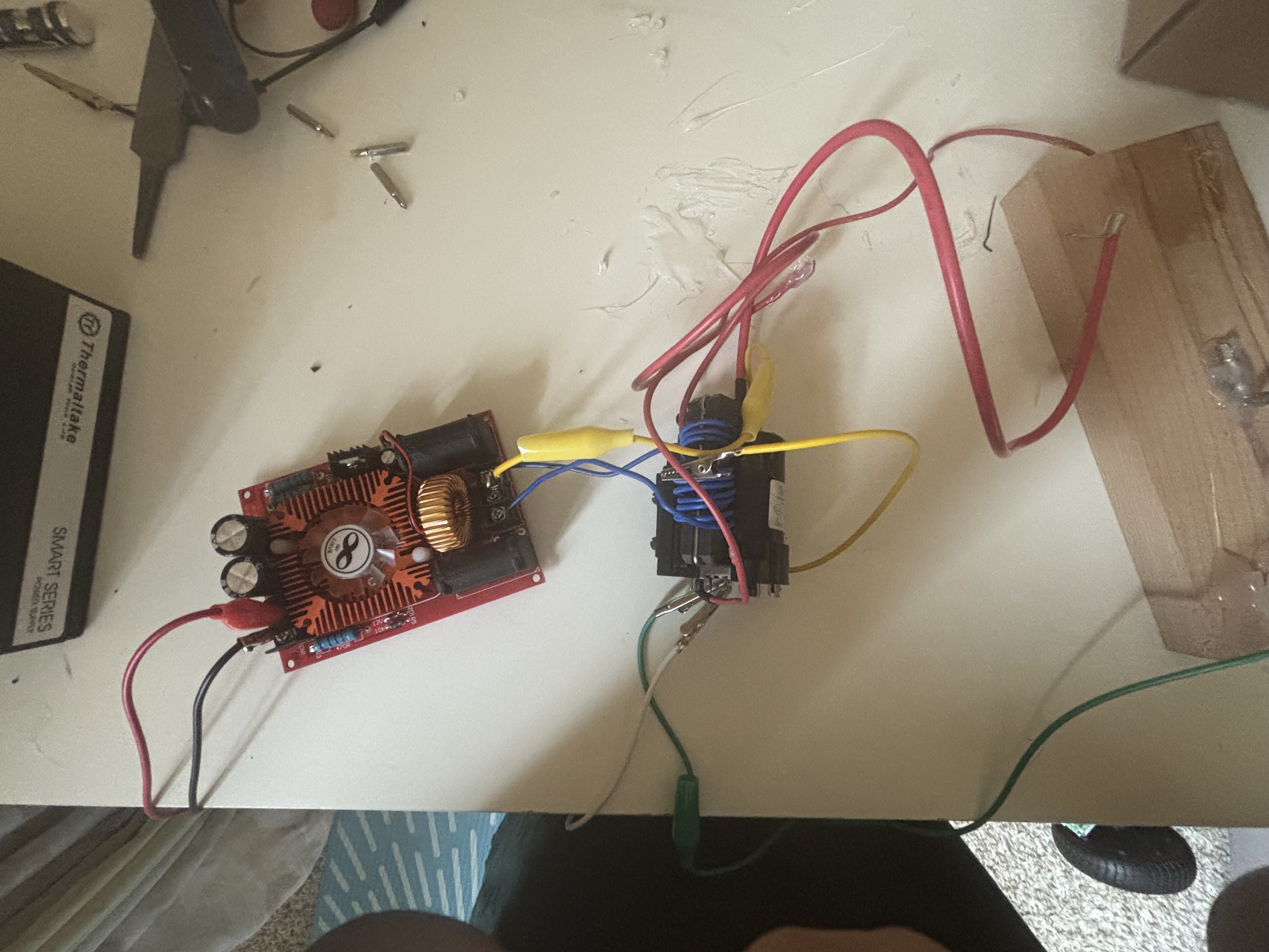
Ours came from a salvaged TV and is marked BSC25-T101A / JF0501-N1156. The primary winding (input) measures about 1.3 ohms of resistance across its two pins, which is typical for a flyback primary. The secondary winding steps that voltage up by a factor of hundreds, producing the high voltage output through the thick suction-cup wire that originally connected to the CRT tube.
The ZVS Driver
The ZVS driver board is what feeds the flyback. ZVS stands for Zero Voltage Switching. The transistors switch at the exact moment the voltage across them is zero, which reduces heat and energy loss compared to regular switching circuits. The result is a highly efficient oscillating current through the flyback primary, which induces the high voltage on the secondary.
Our board runs on 12–30V DC input and draws somewhere around 5–15 amps depending on load. We powered it from a 500W ATX PC power supply, which outputs a rock-solid 12V with over 40 amps of available current on the 12V rail. That’s way more than the ZVS would ever need, but it’s what I had on hand and it meant that the power supply would never be the issue if it weren’t working.
The Arc
When you bring the HV output wire close to a grounded electrode, the electric field between them gets strong enough to ionize the air molecules in the gap. Ionized air becomes a conductor, and current flows through it. That glowing channel is plasma, the fourth state of matter. The arc also produces a loud cracking sound from the rapid expansion of superheated air, and a smell of ozone from the ionization of oxygen molecules.
The Parts
We kept costs low by salvaging where possible. Here’s what the build used:
- Flyback transformer - Amazon
- ZVS driver board - Amazon
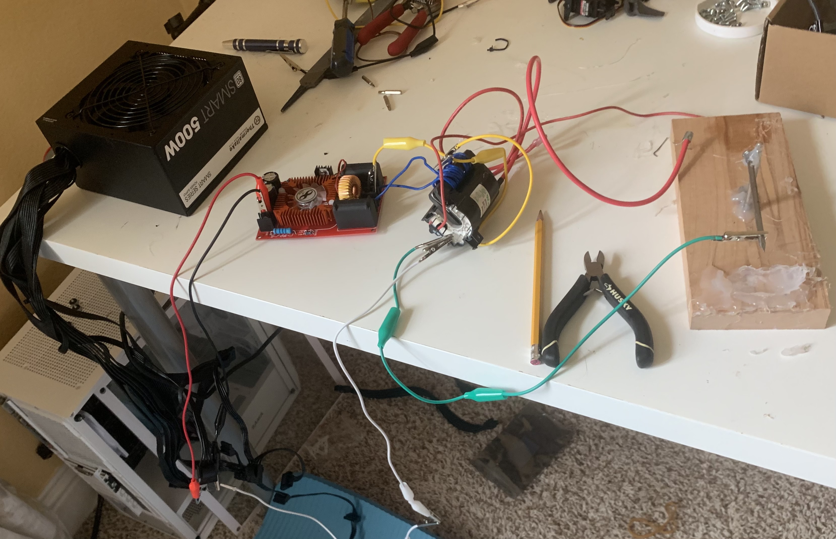
- ATX PC power supply - Thermaltake Smart 500W, repurposed from an old desktop
- Nail - used as the high voltage electrode + ground electrode
- Wood base - non-conductive mounting platform
- Alligator clip leads and jumper wires - for connections
- Hot Glue - Nonconductive, used to connect parts
Total cost ended up around $30, mostly because we had some parts at home.
The Build
Power Setup
The ATX supply needed a small trick to run without a motherboard. Shorting the green PS_ON wire to any adjacent ground wire on the 24-pin connector fools the supply into turning on without the motherboard. From there, we tapped the 12V and ground lines from a Molex connector (the yellow wire is +12V, the black wires are ground), and fed those into the ZVS board’s input terminals.
Wiring the Flyback
This was where most of the troubleshooting happened. The flyback has 10 pins on its base, and only a few are relevant. Through research and resistance testing, we identified:
- Pin 2 — one end of the primary winding → ZVS Signal A
- Pin 4 (B+115V) — other end of the primary winding → ZVS Signal B
- Pin 7 (GND) — primary ground → tied to PSU ground
Resistance between Pin 2 and Pin 4 measured 1.3 ohms, confirming these are the correct primary winding terminals.
The Electrode Setup
The high voltage output wire from the flyback is held by me. The nail is connected to a ground pin on the PSU via alligator clip. When I bring the insulated wire close to the grounded nail, the arc jumps across that gap and completes the circuit back to ground.
Safety
This is worth its own section because 20,000 volts is super dangerous. A few rules we followed:
- One hand rule — when anything is live, one hand stays in a pocket. This prevents current crossing your chest through your heart if you accidentally complete a circuit through your body.
- Work outdoors — the arc produces ozone and nitrogen oxides, which are harmful and potentially cancerous in enclosed spaces.
- Kill power before adjusting anything — and wait a few seconds for capacitors to discharge.
- Never work alone — always have someone else present.
The Result
After sorting out the ZVS board and grounding issues, the moment we brought the HV wire close to the grounded nail, we saw that first purple-white arc snap into place. Holding the insulated wire and drawing out a sustained arc a centimeter or two long, hearing it crack and watching it glow, was easily one of the coolest projects I’ve made.
The arc is estimated at around 20,000 V based on its length, running off a 12V input.
Here’s the video ⬇️